Proper selection of fiber optic cables and connectors for specific uses is becoming more and more important as fiber optic systems become the transmission medium for communications and aircraft applications, and even antenna links. Choices must be made in selecting fiber optic cables and connectors for high-reliability applications. This article provides the knowledge for how to make appropriate selections of fiber optic cable and connector when designing a fiber optic system.
Fiber Optic Cable Selection
To select a fiber optic cable, you have to make choices of both the fiber selection and the cable construction selection.
Fiber Selection
The three major fiber parameters used in selecting the proper fiber for an application are bandwidth, attenuation and core diameter.
Bandwidth: The bandwidth at a specified wavelength represents the highest sinusoidal light modulation frequency that can be transmitted through a length of fiber with an optical signal power loss equal to 50 percent of the zero modulation frequency component. The bandwidth is expressed in megahertz over a kilometer length (MHz/km).
Attenuation: The optical attenuation denotes the amount of optical power lost due to absorption and scattering of optical radiation at a specified wavelength in a length of fiber. It is expressed as an attenuation in decibels of optical power per kilometer (dB/km). The attenuation is determined by launching a narrow spectral band of light into the full length of fiber and measuring the transmitted intensity.
Core Diameter: The fiber core is the central region of an optical fiber whose refractive index is higher than that of the fiber cladding. Various core diameters are available to permit the most efficient coupling of light from commercially available light sources, such as laser diodes. There are two basic fiber types, single-mode and multimode. Single-mode fiber has a core diameter of 8 to 10 microns and is normally used for long distance requirements and high-bandwidth applications. Multimode fiber has a core diameter of 50 or 62.5 microns and is usually used in buildings. The picture below shows single-mode and multimode fiber with different core diameters.

Cable Construction Selection
Another important consideration when specifying optical fiber cable is the cable construction. There are three main types of cable configurations: buffered fiber cable, simplex cable and multichannel cable.
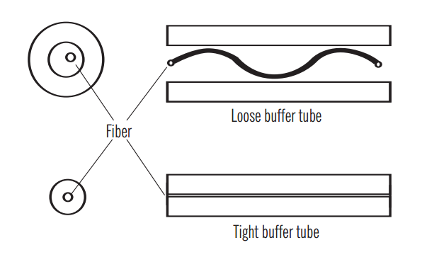
Buffered Fiber Cable: There are two kinds of buffered fiber. The first is a loose buffer tube construction where the fiber is contained in a water-blocked polymer tube that has an inner diameter considerably larger than the fiber itself. The loose buffer tube construction offers lower cable attenuation from a given fiber, and a high level of isolation from external forces. Loose buffer cables are typically used in outdoor applications and can accommodate the changes in external conditions. The second is a tight buffer tube design. A thick buffer coating is placed directly on the fiber. The tight buffer construction permits smaller, lighter weight designs and generally yields a more flexible cable. A comparison of these two cable constructions is shown below.
Simplex Cable: A simplex fiber optic cable has only one tight buffered optical fiber inside the cable jackets. Simplex fiber optic cables are typically categorized as interconnect cables and are used to make interconnections in front of the patch panel. They are designed for production termination where consistency and uniformity are vital for fast and efficient operation.
Multichannel Cable: Building multiple fibers into one cable creates a multichannel cable. This type of cable is usually built with either a central or external strength member and fiber bundled around or within the strength member. An external jacket is used to keep the cable together.
Fiber Optic Connector Selection
Connector is an integral component of the cabling system infrastructure, which keeps the information flowing from cable to cable or cable to device. There are various connector types, including LC, FC, ST, SC, MTRJ, MPO, MTP, DIN, E2000, MU, etc. To design a fiber optic system, optical connector selection is also a very important decision. When selecting an optical connector, you have to take fiber types, polishing styles and number of fibers all into consideration.
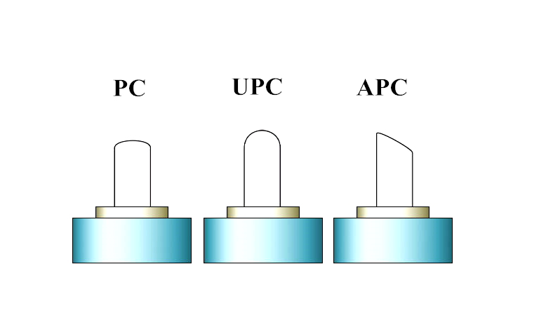
Polishing Styles: There are mainly three kinds of polishing styles, PC (physical contact), APC (angled physical contact), and UPC (ultra physical contact). PC, UPC and APC refer to how the ferrule of the fiber optic connectors is polished. PC connector is used in many applications. UPC connectors are often used in digital, CATV, and telephony systems. APC connectors are preferred for CATV and analog systems. The picture below shows these three kinds of polishing styles.
Fiber Types: Single-mode and multi-mode optical fiber are two commonly used fiber types. Accordingly, there are single-mode optical connector and multi-mode optical connector. ST and MTRJ are the popular connectors for multi-mode networks. LC connector and SC connector are widely used in single-mode systems. Single-mode fiber optic connectors can be with PC, or UPC or APC polish, while multi-mode fiber optic connectors only with PC or UPC polish.
Number of Fibers: Simplex connector means only one fiber is terminated in the connector. Simplex connectors include FC, ST, SC, LC, MU and SMA. Duplex connector means two fibers are terminated in the connector. Duplex connectors include SC, LC, MU and MTRJ. Multiple fiber connector means more than two fibers (for up to 24 fiber) are terminated in the connector. These are usually ribbon fibers with fiber count of 4, 6, 8, 12 and 24. The most popular ribbon fiber connector is MT connector.
Conclusion
The key to designing a successful fiber optic system is understanding the performance and applications of different kinds of fibers, cable constructions and optical connectors, and then utilizing the appropriate components. Fiberstore provides a wide range of fiber optic cables and connectors. Fiber optic cables can be available in single-mode, multimode, or polarization maintaining, and they can meet the strength and flexibility required for today's fiber interconnect applications.
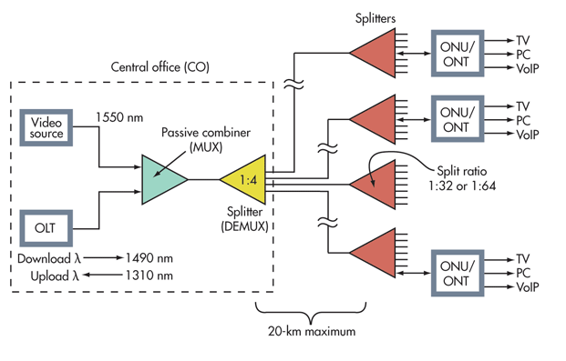
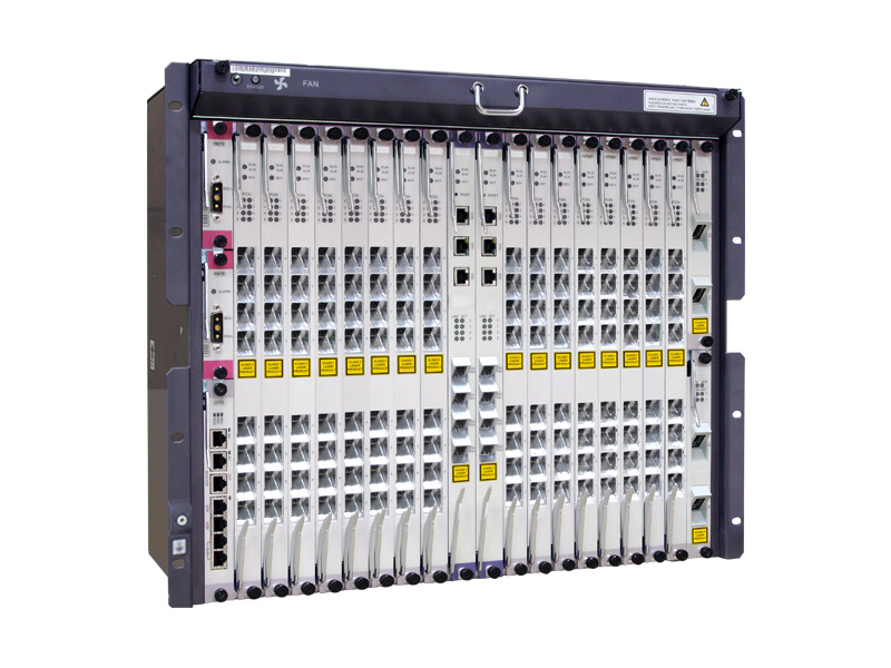 OLT: The optical line terminal is the main element of the network and it is usually placed in the Local Exchange and it's the engine that drives FTTH system. OLT has two float directions: one is upstream getting distributing different type of data and voice traffic from users, the other is downstream getting data, voice and video traffic from metro network or from a long-haul networkand sending it to all ONT modules on the optical distribution network (ODN). The picture on the left shows an OLT.
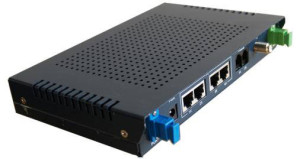 ONU/ONT: Optical network terminals or units are deployed at customer's premises. ONTs are connected to the OLT by means of optical fiber and no active elements are present in the link. A single ONT can serve as point of access for one or multiple customers and be deployed either at customer's premises or on the street in a cabinet. The ONU usually communicates with an ONT, which may be a separate box that connects the PON to TV sets, telephones, computers, or a wireless router. The ONU or ONT can be the same device. The picture on the right shows an ONT.