2015年9月29日星期二

Gigabit Ethernet Cabling Solution

Born in the 1970s, Ethernet technology has continually evolved in order to meet the never-ending requirement for faster rates of data transmission. Through this ongoing evolution, it has matured into the foremost technology standard for local area networks (LANs) as newer, higher performing iterations, such as 1 Gigabit Ethernet and 10 Gigabit Ethernet. There is a variety of types of cables available for making Ethernet connections at speeds of 1 Gigabit and 10 Gigabit per second. This paper provides a brief introduction to these two types of high speed Ethernet cabling solution, 1 Gigabit Ethernet cabling and 10 Gigabit Ethernet cabling.
1 Gigabit Ethernet Cabling
When planning 1 Gigabit Ethernet cabling infrastructure, generally you have two choices: fiber optic or copper. Both offer superior data transmission. From the aspects of fiber cabling choices and copper cabling choices, solutions to 1 Gigabit Ethernet cabling are introduced as follows.
Fiber Cabling Choices
There are two common types of fiber cable available for 1 Gigabit Ethernet, single mode and multi-mode. Both cables provide high bandwidth at high speeds. There are a few other possibilities for range, mode, and wavelength, but the following two are predominate.
  • Short Range: SR—for connections of up to 550 meters in length.
  • Long Range: LR—for connections of up to 10 KM in length.
Fiber optic cable itself and connectors are used for fiber cabling. There are multiple choices for cable type and connector type. Multi-mode fibers and single mode fibers require different connectors. And optical fiber connections are constructed with a combination of a transceiver. The transceiver accepts digital signals from the Ethernet device and converts them to optical signals for transmission over the fiber. SFP (small form factor pluggable transceiver) is the most common type of transceiver used in 1 Gigabit Ethernet connections. The following is a picture of SFP transceiver modules.
SFP Transceivers
Copper Cabling Choices
For 1 Gigabit Ethernet cabling, category 5 cable, commonly referred to as cat5, is a common choice. The cable standard provides performance of up to 100 MHz and is suitable for Gigabit Ethernet. Most cat5 cables are unshielded twisted pair cables, relying on the balanced line twisted pair design and differential signaling for noise rejection. Cat5e, an enhanced version of the category 5 specification was introduced several years ago. Cables of up to 100 meters in length can be used. RJ45 copper SFP transceiver module (Mini-GBIC) is built to offer a cost-effective way to add, replace or upgrade a copper Ethernet port on your networking equipment.
10 Gigabit Ethernet Cabling
10 Gigabit Ethernet cabling is very similar to 1 Gigabit Ethernet cabling. Solutions to 10 Gigabit Ethernet cabling are also introduced in fiber cabling choices and copper cabling choices.
Fiber Cabling Choices
For 10 Gigabit Ethernet cabling, the fiber options are very similar to 1 Gigabit Ethernet cabling. But the range is less due to the higher speed. In general, there are three distance ranges.
  • Short Range: SR—for connections of up to 300 meters in length.
  • Long Range: LR—for connections of up to 2,000 meters in length.
  • Extended Range: ER—for connections of up to 10,000 meters (10 KM) in length.
The transceivers for 10 Gigabit Ethernet cabling are somewhat different. XFP or SFP+ transceivers are used to connect these 10 Gigabit Ethernet cables. The connector type itself defines the mechanical specifications of the fiber-to-transceiver interface. Thus one could have an XFP transceiver on one end of a 10 Gigabit fiber cable and an SFP+ transceiver on the other end. As long as the cable type and connector type match there is no problem. The following is a picture of XFP transceiver module.
XFP
Copper Cabling Choices
As switching standards mature and copper cabling standards catch up, the use of copper cabling for 10GbE is becoming more common. Currently, there are two different copper cabling technologies for 10 Gigabit Ethernet, each with different price and performance capabilities.
10GBase-CX4, published in 2004, was the first 10 Gigabit Ethernet copper standard. CX4 was relatively economical and allowed for very low latency. It uses a coaxial copper cable and can support cable lengths of up to 15 meters. Its disadvantage was a too-large form factor for high density port counts in aggregation switches.
10GBase-T was released in 2006 to run 10 Gigabit Ethernet over cat6a and cat7 copper cabling up to 100 meters. While promising, 10GBase-T still needs technology improvements to lower its cost, power consumption, and latency. Like copper cabling choices for 1 Gigabit Ethernet, 10GBase-T still uses RJ45 copper transceiver to provide reliable connections.
Just as there are many manifestations of 1 Gigabit Ethernet and 10 Gigabit Ethernet standards to suit various networking environments, there are also many copper and fiber cabling technologies to support them. Companies must have a solid understanding of not only their environment and need, but also the different standards and cabling technologies available to them. Doing so will help them develop a sound migration and cabling strategy.
Originally published at www.fiber-optic-cable-sale.com
2015年9月24日星期四

Introduction to Mode Conditioning Patch Cable

Mode conditioning patch cord (MCP) was developed as a solution for network applications where Gigabit Ethernet hubs with laser based transmitters are deployed. It is a special fiber optic patch cord and allows customer upgrading their hardware technology without the cost of upgrading fiber plant. In addition, MCP significantly improves data signal quality while increasing the transmission distance. The text will give some detailed information about mode conditioning patch cable.
What Is Mode Conditioning Patch Cable?
A mode conditioning patch cord is a duplex multi-mode patch cord that has a small length of single mode fiber at the start of the transmission leg, and also a single mode to multi-mode offset fiber connection part in this leg. There are two multi-mode fibers on one end and one multi-mode and one single mode fiber on the other end. It is fully compliant with IEEE 802.3z application standards. Mode conditioning patch cord causes the single mode transceiver to create a launch similar to a typical multi-mode launch. It is designed for long wavelength Gigabit Ethernet applications. The following picture shows the construction of a mode conditioning patch cable.
mode conditioning patch cord
How Does Mode Conditioning Patch Cable Work?
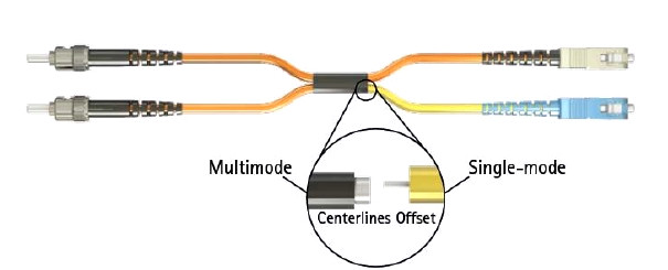
The basic principle behind the cord is that you launch your laser into the small section of single mode fiber. The launch of the light coming out of the equipment begins on a single mode fiber. The other end of the single mode fiber is coupled to multi-mode section of the cable with the core offset from the center of the multi-mode fiber. The light is launched on to the multi-mode fiber at a precise angle, giving the cable its mode conditioning properties. When we use such mode conditioning fiber optic patch cords, we need to connect the yellow leg which is the color of single mode to connect the transmit side of the equipment (single mode Gigabit transceiver) while we connect the orange leg which is the color of multi-mode to the receive side. The picture below shows how the single mode fiber is coupled to multi-mode section of the cable.
Mode Conditioning Fiber Patch Cable
How to Install Mode Conditioning Patch Cable?
To install a mode conditioning patch cable, you need to follow these steps:
  • Step1: Connect the yellow leg (single mode connector) of the MCP cable into the transmit bore of the transceiver.
  • Step2: Connect the rest orange legs (multi-mode connectors) of the MCP cable into the receive bore of the transceiver.
  • Step3: At the other end of the patch cord, put all the orange legs (multi-mode connectors) into the patch panel.
  • Step4: Repeat the above three steps for the second transceiver located at the other end of the network link.
After you have finished all the connection steps above, all the swap of transmit and receiver can only be done at the cable plant side.
Why Do We Need Mode Conditioning Patch Cable?
Transceiver modules used in Gigabit Ethernet (1000 Base-LX) launch only single mode (1300nm) long wave signals, which poses a problem if an existing fiber network utilizes multi-mode cable. When a single mode signal is launched into a multi-mode fiber a phenomenon known as differential mode delay (DMD) can create multiple signals within the multi-mode fiber. This effect can confuse the receiver and produce errors. By allowing the single mode laser launch to be offset away from the center of the multi-mode fiber, mode conditioning patch cord reduces the effect of such differential mode delay and provides a much higher operational bandwidth by precisely aligning a single mode termination at the laser transmitter. This is essential for networks using 62.5/125 and 50/125 multi-mode optical fiber and may be specified for current multi-mode networks depending upon the system requirements.
Mode conditioning patch cables are with various options, from all types of connectors to different jackets and different lengths. A variety of fiber optic connectors are available for your convenience, including: LC/UPC, SC/UPC, FC/UPC, ST/UPC, LC/APC, SC/APC, FC/APC, and MTRJ. Mode conditioning patch cables are built in the form of a simple duplex patch cable, so they can easily be installed in a system without the need for additional components or hardware. Their length can range from one meter and up to support virtually any network topography.
Originally published at www.fiber-optic-cable-sale.com

2015年9月17日星期四

The Basics of PM Fiber Patch Cords

Polarization maintaining (PM) fiber optic patch cord is a kind of special fiber patch cord. It can be used in many areas. Here's what you need to know about PM fiber patch cords if your designs require them.
What is a PM Fiber Patch Cord?
A PM optical fiber is a single mode optical fiber in which linearly polarized light, if properly launched into the fiber, maintains a linear polarization during propagation, exiting the fiber in a specific linear polarization state. PM fiber patch cord is a fiber optic cable made with PM fiber and terminated on both ends with high-quality ceramic fiber connectors. PM fiber patch cord is a base device of optical passive component.
Characteristics of PM Fiber Patch Cords
If the polarization of the input light is not aligned with the stress direction in the fiber, the output light will vary between linear and circular polarization (and generally will be elliptically polarized). And the exact polarization will also be sensitive to variations in temperature and stress in the fiber. The light shall be coupled at the fiber entrance parallel to the slow axis or to the fast axis, then the maintaining of the polarization is therefore possible. It is important to make sure that the polarization of the input light is maintained. PM fiber patch cords maintain the existing polarization of linearly-polarized light that is launched into the fiber with the correct orientation. PM fiber patch cords also feature low insertion loss, high extinction ratio, high return loss, excellent changeability over a wide wavelength range and excellent environmental stability and reliability.
Types of PM Fiber Patch Cords
There are a wide variety of PM fiber patch cords available that support different data rates and suit various connector types. According to different criteria, PM fiber patch cords can be categorized into various types. The following is some detailed information about types of PM fiber patch cords based on 4 different criteria:
Classification by connector type―PM fiber patch cords are capped at both ends with fiber connectors. FC, SC, LC and ST are the commonly used connector types for PM fiber termination. According to the connectors on the both ends, there are many different kinds of PM fiber patch cords, such as LC-FC, SC-FC, or FC-FC PM fiber patch cords.
FC to FC & FC to LC PM Patch Cord

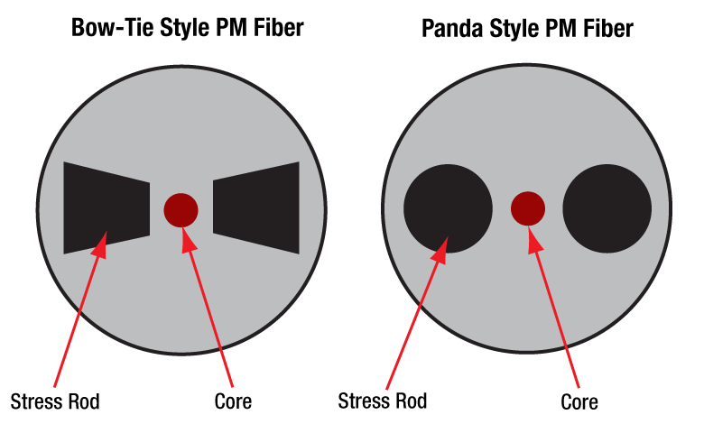
Classification by fiber type―PM fiber patch cords are built with polarization maintaining fiber. To ensure the polarization of both the input and output light in a PM fiber, several different shapes of rod are used, and the resulting fiber is sold under brand names such as "Panda" and "Bow-tie". With different PM fiber, there are corresponding PM fiber patch cords, such as Panda PM fiber patch cords and Bow-tie PM fiber patch cords.
Panda and Bow-tie PM fiber

Classification by cable type―PM fiber patch cords can also be categorized according to the cable types. There are mainly three kinds of cable types, 250um bare fiber, 900um loose tube jacket and 3mm loose tube jacket. So based on the cable types, there are 3 kinds of PM fiber patch cords.
Classification by fiber length―The standard length is 1 meter. It can vary for special requirements. The length of PM fiber patch cords can be custom made.
Applications of PM Fiber Patch Cords
PM fiber patch cords are often used in polarization sensitive fiber optical systems for transmission of light that requires the PM state to be maintained. PM optical patch cord is a special optical component using the properties of optical fibers specially manufactured so that its transmission parameters can support a particular application. They have a large number of uses, including high-data-rate communications systems, polarization sensitive components, and interferometric sensors. They are also widely used in PM fiber amplifiers, fiber lasers, high speed communication systems, testing equipment and instrumentation applications. Area of use of PM fiber patch cords is very broad and includes equipment such as instrumentation, spectroscopy, aerospace, medical diagnostics and many other industrial applications.
Conclusion
Understanding polarization has become a necessity in today's fiber optic communication systems and applications. One must understand how to characterize and handle the effects of polarization in order to maximize the performances of systems involving polarization-sensitive devices. PM fiber patch cord is based on a high precision butt-style connection technique to preserve polarization. It has many types and applications. Knowing more about it can help you to choose.
Originally published at www.fiber-patch-cords.com/blog.html 

2015年9月15日星期二

MTP Fiber Patch Cables Overview

MTP stands for multi-fiber termination push-on connector and is designed by US Conec and built around the MT ferrule. MTP fiber patch cable takes its name from the MTP connector, which allows high-density connections between network equipment in telecommunication rooms. The following text will thoroughly cover types, advantages and applications of MTP fiber patch cords, and solution provided by Fiberstore.

Types of MTP Fiber Patch Cords
There are different types of MTP fiber patch cords based on various criteria. According to the core of the fiber, MTP fiber patch cords are categorized into MTP single mode fiber patch cords and MTP multi-mode fiber patch cords. According to the connectors on both ends, there are mainly two configurations for MTP fiber patch cables. One is the MTP connector to MTP connector, which is often called MTP trunk cable. The other is MTP connector to standard LC/FC/SC/ST/MTRJ connectors (generally MTP to LC), which is often called the MTP harness cable, or MTP fan-out cable. The picture shows a MTP trunk cable and a MTP harness cable.

MTP Trunk Cable and MTP Harness Cable

Advantages of MTP Fiber Patch Cords
The MTP fiber system is a truly innovative group of products which moves fiber optic networks into the new millennium. MTP connector, as a kind of multi-fiber connector, is most commonly used for 12 or 24 fibers. It has about the same size of a SC connector and provides up to 12 or 24 times the density, thereby offering savings in circuit card and rack space. Using MTP trunk cables, a complete fiber optic backbone can be installed without any field termination being required. Moreover, MTP connector is designed as a high-performance version of the multi-fiber push on (MPO) and will interconnect with MPO connectors, so it is compatible with VZ TPR.9431, IEC-61754-7 and EIA/TIA-604-5. It uses a simple push-pull latching mechanism for easy and intuitive insertion and removal.

MTP jumpers utilizes precision ferrules, precise housing dimension and metal guide pins to ensure fiber positioning when mating and give excellent performance. And the easy installation of them saves time and money. They can optimize network performance and maximize lifespan. MTP multi-fiber jumpers deliver the performance and reliability needed in today's demanding high-speed broadband and data networks. They are designed to cater for up-scaling needs and future technologies growth.

Applications of MTP Fiber Patch Cords
The MTP fiber patch cord is the choice for a wide variety of applications. MTP fiber patch cords can be used for backbones, disaster recovery, building fiber optic distribution, quick setup of new wiring hubs, warehouses, direct termination of ribbon cables, repair of plug and play universal system solutions, and parallel optical interconnects between servers.

Besides these general applications above, MTP trunk cable and MTP harness cable, two commonly used MTP fiber patch cords, have their respective special uses. MTP trunk cables are available in 12-144 count. These high count MTP assemblies are ideal for backbone and data center applications that require a high fiber count in a limited space. MTP fan-out assemblies provide connection to equipment or panels that are terminated with ST, SC, FDDI, or ESCON connectors and meet a variety of fiber cabling requirements. Such assemblies are pre-wired available for patch panels and wall enclosures.

Fiberstore MTP Fiber Patch Cables Solution
Fiberstore offers single mode and multi-mode MTP assemblies, such as MTP-LC, MTP-ST, MTP-FC, MTP-MU, MTP-MT-RJ, MTP-E2000, simplex and duplex. Also we provide UPC MTP assemblies and APC MTP cables. All fiber counts are available in plenum, riser, or outdoor ratings to suit different kinds of environment. Our high quality factory pre-termination eliminates the need for costly field termination and testing.

Originally published at www.fiber-patch-cords.com/blog.html

2015年9月11日星期五

Fiber Patch Cords vs Fiber Pigtails

Fiber optic patch cord and fiber optic pigtail are two commonly used components in fiber optic network. They have many things in common and they also differ in distinct ways. Knowing both the similarities and the differences between them will help you make the best selection for your project. The passage mainly talks about their similarities and differences in both structures and applications.
Structures of Fiber Patch Cords and Pigtails
Fiber patch cord, also known as fiber optic patch cable or fiber jumper cable, is a short length of optical fiber cable with a connector on each end. Connector types on each side of the fiber patch cable can be different and they can also be the same. Fiber optic pigtail is a piece of cable terminated with a fiber optic connector at only one end of the cable and leaves a length of exposed fiber at the other end, so that the connector side can link to the equipment and the other side can be melted with optical cable fibers or stripped and fusion spliced to a single fiber of a multi-fiber trunk. The following picture shows a fiber patch cord and a fiber pigtail.
fiber patch cord and pigtail
Fiber optic patch cords and pigtails structurally have much in common. They are both available in single mode and multi-mode, and they can be made into simplex and duplex. Besides, both fiber patch cord and pigtail can terminate with many kinds of fiber optic connectors, including FC, SC, ST, LC, MTRJ, MPO, MU, SMA, FDDI, E2000, DIN4, and D4.
The major physical difference between fiber patch cord and pigtail is that fiber patch cord is a fixed length piece of cable with fiber connectors on each end while fiber pigtail has fiber connectors on only one end of the cable. Fiber optic patch cords can be cut into shorter lengths to make two pigtails.
Applications of Fiber Patch Cords and Pigtails
Fiber optic patch cords and pigtails provide interconnect and cross-connect of applications over installations in entrance facilities, telecommunications rooms, and data centers. They are available in OM4, OM3, OM2, OM1, or OS1/OS2 fiber types to meet the demands of Gigabit Ethernet, 10 Gigabit Ethernet and high speed Fibre Channel. However, they have their respective application areas, too.
Fiber patch cords are commonly used to connect ports on fiber distribution frames. They support network applications in main, horizontal and equipment distribution areas and are available in optical fiber riser cable (OFNR), and low smoke zero halogen (LSZH) rated jacket materials to comply with local cabling ordinances. They also support high speed (10/40 Gbs) telecommunications. Fiber optic patch cords can be used in many areas, such as integrated optics, laser detection and display, and materials processing.
Fiber optic pigtails support fusion splice field termination applications. They should be installed where they will be protected and spliced, so they are usually used with fiber optic management equipment like optical distribution frame (ODF), splice closures and cross cabinets. Pigtails are found anywhere, but most commonly in optical assemblages or optical components. There are waterproof fiber optic pigtails used for outdoor applications, which is with thick poly ethylene (PE) jacket and big diameter.
Fiberstore produces high quality fiber optic patch cords and pigtails using a variety of commercially available connectors and fibers. We provide various single mode and multi-mode fiber patch cords and fiber pigtails. These patch cords and pigtails offer low insertion losses, and excellent repeatability. And they can be manufactured to custom length.
Originally published at www.fiber-patch-cords.com/blog.html

2015年9月8日星期二

How to Install Fiber Optic Connectors?

As we know, fiber optic patch cords are capped at both ends with fiber optic connectors to allow them to be rapidly and conveniently connected to telecommunication equipment. Fiber optic connector is one of those high quality ceramic components used to achieve accurate and precise connections of the fiber ends. It is a simple device which allows fiber links to be readily connected and disconnected.
How to install fiber optic connectors to optical fibers so that they can achieve accurate and precise connections? The method for attaching fiber optic connectors to optical fibers varies based on connector types. Installation ways of fiber optic connectors largely depends on the connector types. Generally, connectors can be categorized into no-epoxy/no-polish connectors and epoxy-and-polish connectors. The following text elaborates on how to install these two kinds of connectors respectively.
No-epoxy/no-polish Connector Installation
 
How to install no-epoxy/no-polish (NENP) connectors to optical fibers? A no-epoxy/no-polish connector includes an precisely polished endface. When installing an NENP connector, there is no need to use an epoxy or to polish the endface. The field fiber is mechanically spliced to a factory-cleaved fiber stub. The following picture is an illustration of  no-epoxy/no-polish connector installation.
No epoxy no polish Connector
The installation process begins with preparing the field fiber, which is done by stripping the protective coating down to the bare glass. Once the fiber is cleaned, it is then cleaved with a precision cleaver. Next step is to insert the field fiber into the connector until it is seated against the factory-stubbed fiber and locked into place mechanically by a rotating cam or other means. Typically this step is achieved by using a tool that holds the connector and activates the mechanical splice by a button or lever.
Epoxy-and-polish Connector Installation
 
How to install epoxy-and-polish (EP) connectors to optical fibers? The most common types of EP connectors use heat- or anaerobic-curing techniques. A heat-cure connector uses heat to harden an epoxy, which takes several minutes. An anaerobic EP connector uses a two-part epoxy, a hardener that is inserted into the connector and an activator on the fiber.
To install an EP connector, an epoxy must be inserted into the connector ferrule first to form a bond between the field fiber and the connector's ferrule, and then the endface needs to be hand-polished. Next, the field fiber is stripped down to the bare glass and cleaned. If the connector is heat-cure, the fiber is inserted into the connector and placed in an oven for the epoxy to cure. If the type of connector is anaerobic, the bare fiber is painted with an activator and inserted into the connector. Once the epoxy has been cured, the fiber stub which is protruding above the ferrule is scribed and removed. The final step is to polish the endface of the connector using a fixture and several different polishing films.
Notes for Fiber Optic Connector Installation
 
Besides different installation methods for different connector types, several things need to be paid attention to when installing fiber optic connectors, especially when a fiber patch cord has two different types of connectors, such as LC-SC fiber optic patch cord or FC-ST fiber optic patch cord.
• The bared fiber must be thoroughly cleaned with fiber optic cleaning fluid. Never clean the fiber with a dry tissue. Before the connection is made, the end of each fiber must have a smooth finish that is free of defects such as hackles, lips, and fractures.
• The cable should be cut about one inch longer than the required finished length.
• Be sure to use strippers made specifically for use with fiber rather than metal wire strippers because damage can occur and then weaken the fiber.
Any problems with a connector, such as poor installation and uncleanness, can greatly influence the transmission and reception of the light power. And such problems may render the fiber optic system inoperative. So it is very necessary to know something about installation of fiber optic connectors.
Originally published at www.fiber-patch-cords.com/blog.html

2015年9月2日星期三

Fiber Optic Connectors ― an Essential Part of Fiber Patch Cords

As we know, fiber patch cords are capped at both ends with fiber optic connectors to allow them to be rapidly and conveniently connected to telecommunication equipment and to achieve accurate and precise connections. Fiber optic connector is a very important part of the fiber patch cords. This article mainly talks about what fiber optic connector is, four common types of fiber optic connectors and its relationship with fiber patch cords.
What Is Fiber Optic Connector
This question can be answered in two ways. Functionally, a fiber optic connector terminates the end of an optical fiber, and provides a separable connection between two elements of an electronic system without unacceptable signal distortion or power loss. Structurally, every connector includes several parts, two permanent interfaces, the contact springs in each half of the connector, the separable interface and the connector housing which maintains the location of the contacts and isolates them from one another electrically. The connectors mechanically couple and align the cores of fibers so light can pass. To achieve less light loss, more and more better connectors are made to provide more accurate misalignment of the fibers.
Four Common Types of Fiber Optic Connectors
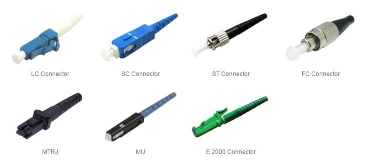
Connector types of the patch cable must match the patch panels and equipment so that the patch cable can function well. There are many different connectors in use for fiber optic patch cords. The text below is a brief overview of four common connector types. The following picture shows some common fiber optic connectors.
Fiber Optic Connector
LC connector is a small form factor plastic push/pull connector with a 1.25mm ferrule. LC was first developed by Lucent. LC connector has a locking tab and a plastic housing and provides accurate alignment via its ceramic ferrule. LC has been referred to as a miniature SC connector.
SC connector is a plastic push/pull connector with a 2.5mm ferrule. It requires less space in patch panels than screw on connectors. For its low cost, simplicity and durability, SC connector is the second most commonly used type for polarization maintaining (PM) connections. Like LC connector, SC connector also has a locking tab and provides accurate alignment via its ceramic ferrule.
FC connector is a metal screw on connector with a 2.5mm ferrule. It is extensively used at the interfaces of test equipment due to its ruggedness. FC connector is the most common connector used for PM connections. And it features a metal housing, a position locatable notch and a threaded receptacle. FC connectors are nickel-plated.
ST connector is a metal bayonet coupled connector with a 2.5mm ferrule. It can be inserted into and removed from a fiber optic cable both quickly and easily. ST connectors are nickel-plated, keyed, spring-loaded and constructed with a metal housing. It has push-in and twist types.
All these four types of fiber optic connectors have different constructions and their respective applications. And there are many other kinds of fiber optic connectors, such as MU, MTRJ, E2000, SMA, etc. One important criterion for choosing fiber patch cord is to choose one with the most appropriate connector type that meets your needs.
Fiber Optic Connectors and Fiber Patch Cords
Fiber optic connector is an essential part of fiber patch cords. Generally, many fiber optic connectors can be manufactured for both single mode and multi-mode, simplex and duplex fiber patch cables. And fiber patch cord can have the same or different connectors at its both ends. For example, LC-LC single mode simplex fiber patch cord is a single mode simplex fiber patch cable with a simplex LC connector on each end, or SC-LC multi-mode duplex fiber patch cord is a multi-mode duplex fiber patch cable with a duplex LC connector on one end and a duplex SC connector on the other end.