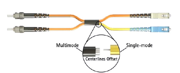
Optical fiber is now an effective high-capacity data communication medium for it can support long distance transmission. It is a fiber constructed of glass or plastic, which does not contain any metal material and thus avoids Electro-Magnetic Interference (EMI) and distortion of information along with the distance. This results in high accuracy of data along the transmission cable. The data is modulated within the light waves. There are mainly two modes of cables available: single-mode and multi-mode. Multi-mode patch cord is multi-mode fiber cable terminated at both ends with fiber optic connectors. In this article, detailed information about multi-mode patch cords will be given to help you get a better understanding of them.
What Is Multi-mode Patch Cord?
Multi-mode patch cord is usually 50/125 and 62.5/125 microns in construction (shown in the following figure). The numbers 50 μm and 62.5 μm refer to the diameters of the glass or plastic core, the part of the fiber that carries the light which encodes your data. The number 125μm is the diameter of the cladding, which confines the light to the core because it has a lower index of refraction. The transition between the core and cladding can be sharp, which is called a step-index profile, or a gradual transition. The two types have different dispersion characteristics and thus different effective propagation distance. Multi-mode fiber cables may be constructed with either graded or step-index profile, and those with graded index fiber is better in accuracy and performance.
Multi-mode patch cord has a larger core diameter than single mode patch cable, allowing multiple modes of light to propagate. Due to this, the number of light reflections created as the light passes through the core increases, creating the ability for more data to pass through at a given time. Multi-mode patch cord has high dispersion and attenuation rate, which means the quality of the signal is reduced over long distances. Multi-mode patch cord is typically used for short distance transmission, for usually a distance less than 500 meters, such as data and audio/video applications in local area networks (LANs).
Types of Multi-mode Patch Cord
Multi-mode fiber optic cable is described using a system of classification determined by the ISO 11801 standard—OM1, OM2, and OM3—based on the modal bandwidth of multi-mode optical fiber. OM4, defined in TIA-492-AAAD by the TIA, was finalized in 2009. "OM" stands for optical multi-mode. Technically, OM1/OM2/OM3/OM4 multi-mode fiber did not define a specific fiber size, but rather their optical channel performance.
OM1 specifies 62.5μm fiber core size and OM2 specifies 50μm fiber core size. They are commonly used in premises applications supporting Ethernet rates of 10 Mbps to 1 Gbps, not suitable enough for today's higher-speed networks. They were ideal for use with LED transmitters. OM3 and OM4 specify an 850nm laser-optimized 50μm cable. They are both laser-optimized multi-mode fiber (LOMMF) and were developed to accommodate faster networks such as 10 Gbps, 40 Gbps, and even 100 Gbps. OM1/OM2/OM3/OM4 can sometimes be distinguished by jacket color: orange jackets for 62.5/125μm OM1 fiber and 50/125μm OM2 fiber, and aqua is recommended for 50/125μm "laser-optimized" OM3 and OM4 fiber.
Comparison Between OM3 and OM4
Both OM3 and OM4 are laser-optimized high bandwidth 50µm multi-mode fiber. The requirements of the OM4 standard are identical to OM3 with the sole exception of the bandwidth values. Both 850nm EMB and 850nm over-filled launch (OFL) bandwidth have been increased from the OM3 requirements. OM3 with a effective modal bandwidth of 2000 MHz·km and OM4 with an effective modal bandwidth of 4700 MHz·km. Laser optimized 50µm multi-mode fiber is the recommended fiber type in today's LAN and data center environments in conjunction with 850nm vertical-cavity surface-emitting lasers (VCSELs). For prevailing 10Gb transmission speeds, OM3 is generally suitable for distances up to 300 meters, and OM4 is suitable for distances up to 550 meters. With the spread of 40 and 100 Gigabit Ethernet, OM3 and OM4 also are only well positioned to support these burgeoning data rates over distances of 100m and 150m respectively. OM4 supports the majority of data center links that utilize 40 and 100 GbE in high-speed/high-performance computing applications driven by server virtualization, cloud computing, streaming video, and ever increasing IP traffic and convergence.
Conclusion
Multi-mode patch cord is a commonly used fiber optic jumper type for short distance transmission. And there are mainly four different kinds of multi-mode patch cord, OM1 multi-mode patch cord, OM2 multi-mode patch cord, OM3 multi-mode patch cord, and OM4 multi-mode patch cord. These four kinds of multi-mode patch cords have their own special applications. You can choose from according to your own needs.

