2016年5月31日星期二

How Much Do You Know About Multi-mode Patch Cord?

Optical fiber is now an effective high-capacity data communication medium for it can support long distance transmission. It is a fiber constructed of glass or plastic, which does not contain any metal material and thus avoids Electro-Magnetic Interference (EMI) and distortion of information along with the distance. This results in high accuracy of data along the transmission cable. The data is modulated within the light waves. There are mainly two modes of cables available: single-mode and multi-mode. Multi-mode patch cord is multi-mode fiber cable terminated at both ends with fiber optic connectors. In this article, detailed information about multi-mode patch cords will be given to help you get a better understanding of them.

What Is Multi-mode Patch Cord?
Multi-mode patch cord is usually 50/125 and 62.5/125 microns in construction (shown in the following figure). The numbers 50 μm and 62.5 μm refer to the diameters of the glass or plastic core, the part of the fiber that carries the light which encodes your data. The number 125μm is the diameter of the cladding, which confines the light to the core because it has a lower index of refraction. The transition between the core and cladding can be sharp, which is called a step-index profile, or a gradual transition. The two types have different dispersion characteristics and thus different effective propagation distance. Multi-mode fiber cables may be constructed with either graded or step-index profile, and those with graded index fiber is better in accuracy and performance.

multimode fiber cable

Multi-mode patch cord has a larger core diameter than single mode patch cable, allowing multiple modes of light to propagate. Due to this, the number of light reflections created as the light passes through the core increases, creating the ability for more data to pass through at a given time. Multi-mode patch cord has high dispersion and attenuation rate, which means the quality of the signal is reduced over long distances. Multi-mode patch cord is typically used for short distance transmission, for usually a distance less than 500 meters, such as data and audio/video applications in local area networks (LANs).

Types of Multi-mode Patch Cord
Multi-mode fiber optic cable is described using a system of classification determined by the ISO 11801 standard—OM1, OM2, and OM3—based on the modal bandwidth of multi-mode optical fiber. OM4, defined in TIA-492-AAAD by the TIA, was finalized in 2009. "OM" stands for optical multi-mode. Technically, OM1/OM2/OM3/OM4 multi-mode fiber did not define a specific fiber size, but rather their optical channel performance.

OM1 specifies 62.5μm fiber core size and OM2 specifies 50μm fiber core size. They are commonly used in premises applications supporting Ethernet rates of 10 Mbps to 1 Gbps, not suitable enough for today's higher-speed networks. They were ideal for use with LED transmitters. OM3 and OM4 specify an 850nm laser-optimized 50μm cable. They are both laser-optimized multi-mode fiber (LOMMF) and were developed to accommodate faster networks such as 10 Gbps, 40 Gbps, and even 100 Gbps. OM1/OM2/OM3/OM4 can sometimes be distinguished by jacket color: orange jackets for 62.5/125μm OM1 fiber and 50/125μm OM2 fiber, and aqua is recommended for 50/125μm "laser-optimized" OM3 and OM4 fiber.

Comparison Between OM3 and OM4
Both OM3 and OM4 are laser-optimized high bandwidth 50µm multi-mode fiber. The requirements of the OM4 standard are identical to OM3 with the sole exception of the bandwidth values. Both 850nm EMB and 850nm over-filled launch (OFL) bandwidth have been increased from the OM3 requirements. OM3 with a effective modal bandwidth of 2000 MHz·km and OM4 with an effective modal bandwidth of 4700 MHz·km. Laser optimized 50µm multi-mode fiber is the recommended fiber type in today's LAN and data center environments in conjunction with 850nm vertical-cavity surface-emitting lasers (VCSELs). For prevailing 10Gb transmission speeds, OM3 is generally suitable for distances up to 300 meters, and OM4 is suitable for distances up to 550 meters. With the spread of 40 and 100 Gigabit Ethernet, OM3 and OM4 also are only well positioned to support these burgeoning data rates over distances of 100m and 150m respectively. OM4 supports the majority of data center links that utilize 40 and 100 GbE in high-speed/high-performance computing applications driven by server virtualization, cloud computing, streaming video, and ever increasing IP traffic and convergence.

Conclusion
Multi-mode patch cord is a commonly used fiber optic jumper type for short distance transmission. And there are mainly four different kinds of multi-mode patch cord, OM1 multi-mode patch cord, OM2 multi-mode patch cord, OM3 multi-mode patch cord, and OM4 multi-mode patch cord. These four kinds of multi-mode patch cords have their own special applications. You can choose from according to your own needs.
2016年5月23日星期一

Selecting Proper Fiber Jumpers for 40G QSFP+ Modules

Many servers in data center can support 40G Ethernet transmissions now. 40Gb QSFP+ is considered to be an economical solution for 40G transmission in data center. And to make them run normally and effectively, fiber patch cables must be used to connect those QSFP+ transceivers plugged in Ethernet switches, as shown in the following picture. As the structure of a 40G transmission is more complex, the selection of fiber patch cords for 40G QSFP+ optics becomes more difficult. This article focuses on how to select proper fiber jumpers for 40G QSFP+ transceivers.
Before jumping to a conclusion, numerous things need to be taken into consideration when selecting a fiber patch cable for a 40G QSFP+ transceiver in practical cabling. In this article, three factors are introduced: the cable type of fiber patch cords, the connector type of fiber patch cords, and ports of switches that need to be connected.
Cable Type
The first factor to consider is the cable type. Optical signals with the same wavelength perform differently when they run through different types of cables. For example, can a 40GBASE QSFP+ transceiver working on wavelength of 850nm be used with OM1 fiber patch cords? Usually, signals with wavelength of 850nm are transmitted over short distance. Thus selecting a multimode fiber patch cord will be more economical. OM1 fiber patch cables are ususally suggested for 100Mb/s and 1000Mb/s networks, and cannot support 40G transmission, because the transmission distance reduces as the data rate raises. OM3 fiber patch cables and OM4 fiber patch cables, these two types of optimized multimode fiber optic cables, are recommended for your 40G transmissions over short distance. And for long distance transmission, you can choose single-mode fiber patch cables.
Connector Type
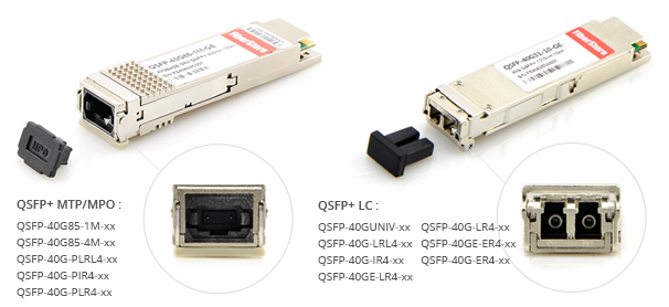
The second factor to consider is what types of connectors are attached on both ends of fiber patch cords. Connector types are usually decided by the interfaces of 40G optical transceivers. Usually, 40G QSFP+ transceivers for short distance are armed with MPO interfaces, and for long distance transmission usually employ LC interfaces. For example, Avago AFBR-79E3PZ compatible 40GBASE-SR4 QSFP+ transceiver has MTP/MPO interface, and can support up to 400m over OM4 MMF. However, there are also exceptions. 40G QSFP+ transceivers like 40GBASE-PLR4 QSFP+ transceiver and 40GBASE-PLRL4 QSFP+ transceiver, they are with MPO interfaces but they can support transmission over long distance. One characteristic of MPO connector is high density which can perfectly satisfy the requirements of 40G transmission. But this kind of connection makes the polarity complex. So when selecting this kind of fiber patch cord, it is very necessary to take the polarity into consideration. The picture below shows 40G QSFP+ transceivers with MPO interfaces and LC interfaces.
QSFP+ transceiver with MPO or LC interface
Switch Ports
The third factor is ports of switches that need to be connected. During practical cabling, two situations are common. One is 40G QSFP+ to 40G QSFP+ cabling and the other is 40G QSFP+ to 10G SFP+ cabling. For 40G QSFP+ to 40G QSFP+ cabling: 40GBASE-SR4 QSFP+ transceiver can be used with OM3 fiber patch cable with MPO interfaces to support up to 100m, and with OM4 fiber patch cable with MPO interfaces to support up to 150m; 40GBASE-LR4 QSFP+ transceiver can be used with single-mode fiber patch cables with LC connectors to support up to 10km. For 40G QSFP+ to 10G SFP+ cabling, fan out patch cable with MPO connectors on one end and four LC duplex connectors on the other end is suggested.
Conclusion
When choosing a fiber patch cord for a 40G QSFP+ transceiver, you need to consider these three factors, the cable type, the connector type and the switch ports. You have to figure out first whether you need single-mode fiber patch cords or multi-mode fiber patch cords, MPO connectors or LC connectors, or QSFP+ to QSFP+ cabling or QSFP+ to 4SFP+ cabling. Fiberstore can provide you with professional one-stop service including the cost-effective and reliable network designing and 40G products.

2016年5月16日星期一

100G Optical Transceivers Overview

To meet the increasing demands for higher speeds and greater scalability, many service providers and enterprise data centers are undergoing an infrastructure transformation to get higher levels of performance and reliability. Optical transceiver is an integral part of overall system design to achieve high performance. 40G and 100G fiber optic transceivers, such as Cisco CFP-40G-LR4 CFP transceiver, and Dell CFP-100G-LR4 CFP transceiver, have become preferable choices for more and more data centers as 1G and 10G cannot meet the their needs of bandwidth-hungry applications. Adopting 100G transceivers not only accelerates data flow throughout your data center or enterprise, but also provides CAPEX (capital expenditures), OPEX (operating expenditures) and time savings. This article talks about options of 100G transceiver modules for your applications.

100G CFP/CFP2/CFP4 Transceiver
When the IEEE finished the first 100G standard for Ethernet networks, the transceiver industry launched an alphabet soup of form factors. The CFP transceiver emerged first. "C" stands for 100, and FP for "form-factor pluggable". CFP transceiver is specified by multi-source agreement (MSA) between competing manufacturers. CFP transceiver was designed after SFP interface, but it is significantly larger to support 100 Gbit/s data rates. While the electrical connection of a CFP transceiver uses 10 x 10 Gbit/s lanes in each direction (RX, TX), the optical connection can support both 10 x 10 Gbit/s and 4 x 25 Gbit/s variants of 100 Gbit/s interconnects.

With improvements in technology, CFP2 and CFP4 specifications have appeared to allow higher performance and higher density. Having similar electrical connection with a CFP transceiver, CFP2 transceiver and CFP4 transceiver specify a form-factor of 1/2 and 1/4 respectively in size of a CFP transceiver. These three modules are not interchangeable, but would be inter-operable at the optical interface with appropriate connectors.

100G-CFP

100G QSFP28 Transceiver
100G QSFP28 transceiver is the exact same footprint as the 40G QSFP+ transceiver. The "Q" is for "quad". Just as a 40G QSFP+ transceiver is implemented using four 10 Gbit/s lanes, 100G QSFP28 transceiver is implemented with four 25 Gbit/s lanes. With an upgraded electrical interface to support signaling rates up to 28 Gbit/s, 100G QSFP28 transceiver makes it as easy to deploy 100G networks as 10G networks. Compared to other transceiver alternatives, 100G QSFP28 transceiver increases density and decreases power and price per bit. It has become the universal data center form factor.

QSFP28 transceiver has several advantages. QSFP28 transceiver increases front-panel density by 250% over QSFP+ transceiver. The form factor and the maximum number of ports are the same, but the lane speeds are increased from 10 Gbit/s to 25 Gbit/s. The increase in panel density is even more dramatic when compared to some other 100 Gbit/s form factor: 450% versus the CFP2. QSFP28 transceivers can be based on either VCSELs (for shorter distances on multimode fiber) or silicon photonics (for longer distances on single-mode fiber). The advent of silicon photonics enables QSFP28 transceivers to support any data center to reach up to 2 km or more. Silicon photonics provides a high degree of integration. The picture below shows a 100G QSFP28 SR4 transceiver.

QSFP28 100GBASE-SR4 850nm 100m Transceiver

100G Transceiver Solutions from Fiberstore
Fiberstore is a professional manufacturer and supplier in optical communication industry. We provide a complete range of 100G optical transceivers for your data center applications. We have sufficient supply of CFP and CFP2 modules, which can be shipped immediately after ordering. For 100G QSFP28 transceivers, we have 100GBASE-SR4 QSFP28 transceivers and 100GBASE-LR4 QSFP28 transceivers. With our serious cost control, the prices of all our 100G fiber optic transceivers are much more affordable than the similar products in the market and they can be compatible with many major brands. For more details, please visit www.fs.com or contact over sales@fs.com.

2016年5月11日星期三

Testing and Verification of 3rd-party Optical Transceivers

3rd-party fiber optic transceivers has now been perferable and widely used as optical transmission solutions. High quality and high performance compatible 3rd-party optical transceivers can meet your needs for your applications, such as Intel E10GSFPSR compatible 1000BASE-SX and 10GBASE-SR SFP+ transceiver, or Finisar Intel FTLX8571D3BCV-IT compatible 10GBASE-SR and 1000BASE-SX SFP+ transceiver, which are with high performance and can save you money at the same time. To ensure the compatibility of 3rd-party optical transceivers, they need to be carefully and thoroughly tested and verified. This post will talk about several testing and verification methods of 3rd-party optical transceivers.

Popularity of 3rd-Party Optical Transceivers
Nowadays, more and more companies or users prefer to choose 3rd-party optical transceivers. The increasing market demands for 3rd-party optical transceivers illustrate this point. An officially-branded transceiver and a 3rd-party plug has actually no big difference. As long as optical transceivers meet the same international standards, there is no question of compatibility between fiber optic transceiver modules. Most "third party" optical transceivers are made and assembled in exactly the same plants assembling officially-branded transceivers. The primary benefit of using third party optical transceivers is the cost savings. The difference in price often exceeds 80 percent or more. Cost of optical transceivers is a significant part of the total system expenditure. It is important for designers to minimize the cost. Significant savings brought by third party optical transceivers can enable designers to re-invest and make their designs better. This is why 3rd-party optical transceivers have been increasingly popular with users. The following picture shows an HP JD089B compatible 1000BASE-T SFP copper transceiver. It is fully compatible with HP devices.

HP JD089B compatible 1000BASE-T SFP copper transceiver

Methods of Testing and Verification
Before inserting a 3rd-party optical transceiver module into your network, it is very necessary to test and verify that the 3rd-party optical transceiver module can function well and will not do any damage to your network. There are several methods to test and verify 3rd-party optical transceiver modules, but it is not always as easy as it seems. Here is what you need to know if you are considering testing and verifying 3rd-party optical transceiver modules.

1. Test Bit-Error Ratio: You must always operate within an acceptable bit-error ratio (BER) in a digital communication system. Whether you are testing an interface bus in a laptop computer or a telecommunications link, you have to follow this rule. Generally, in a digital communication system, it should be no more than one error in 1012 bits. If the desired BER is not reached, you should check the transmitter, or the receiver, or both.

2. Test Minimal Power Level and Jitter Level: A receiver needs to achieve a minimum power level to achieve the BER target. The level achieved will dictate the minimum allowed output power. Likewise, if the receiver can only achieve a certain level of jitter, this will be used to define the maximum amount of jitter that can be received from the transmitter without malfunctioning. Transmitter parameters may specify the wavelength and the output waveform shape.

3. Test Interoperability with a Worst-Case Transmitter: Network specifications should determine whether a worst-case transmitter will interoperate with a receiver. Transmitters should also have a signal sufficient enough to support the worst-case transceiver.

4. Verify Compliance with Multiple Samples: Several waveform samples are required to remain compliant. Sometimes, a larger population of waveform samples will provide an accurate assessment of transmitter performance. The oscilloscope will collect more data, but more samples will contribute to the increase of likelihood of mask violations. The results are either pass or fail, so it is important to acquire as many samples as possible to get an accurate assessment, which requires aligning the mask to the waveform.

5. Understand Instrumentation Effects: Keep in mind that any transceiver test can be skewed due to the oscilloscope's frequency response. You can achieve consistent results with a reference receiver. Most tests will use a fourth-order Bessel filter response, and the 3-dB bandwidth is at 75 percent of the data rate.

6. Consider Expanding Your Eye Mask: When you expand the eye mask, you can verify a compliant hit ratio. Only a small number of samples are capable of intersecting a mask. Most oscilloscopes will include a modified version of the classic eye-mask test. Once you have the desired number of samples, you can determine how far you can expand the mask. Each test will determine how far you can expand the mask before the mask hits to the total waveform exceeds the ratio.

Conclusion
Several methods to test and verify third-party optical transceiver modules are introduced above. Hope that they can help you avoid pitfalls, and assist you to test and verify your 3rd-party optical transceivers with ease. It is a necessary step to test and verify third-party optical transceiver modules before using them in a network.

2016年5月4日星期三

QSFP+ DACs and AOCs for 40G Migration

Gradually, 1G and 10G data rates are becoming not adequate enough to meet the ever-growing needs of high-bandwidth applications. Now 40G Ethernet has been the trend. 40G Ethernet is actually a transitional phase. There are practical reasons for its popularity. Products for 40G Ethernet such as 40G QSFP+ transceivers, 40G QSFP+ direct attach copper (DAC) cables and active optical cables (AOCs) are very popular in the market. 40G QSFP+ DACs and QSFP+ AOCs are cost-effective alternative solutions in short reach interconnections. In this post, a detailed introduction to 40G QSFP+ DACs and QSFP+ AOCs will be given.

What Are QSFP+ DACs and QSFP+ AOCs?
40G QSFP+ DACs and QSFP+ AOCs are two kinds of optical transceiver assemblies, which are terminated with transceiver-style plugs to be used in the same ports where optical transceivers are used. QSFP+ AOCs, such as Cisco QSFP-H40G-AOC1M compatible 40G QSFP+ AOC, are active devices, which incorporate active electrical and optical components to boost/receive signal via optical fiber. QSFP+ DACs can be both passive and active. Passive DACs (often called PCCs), such as Cisco QSFP-4SFP10G-CU3M compatible 40G QSFP+ to 4x10G SFP+ passive DAC, have no active circuitry, which means there is a direct connection between copper cable and QSFP+ transceiver's printed circuit board (PCB) electrical contacts. Active DACs (often called ACCs) incorporate active component to boost/receive signal via copper cable. The following picture shows the general internal structure of AOCs and DACs.
AOC-and-DAC
QSFP+ DACs VS QSFP+ AOCs
QSFP+ DACs and QSFP+ AOCs are ideal solutions for short-distance interconnection, and they are widely used in data centers. This part will talk about advantages and disadvantages of QSFP+ DACs and QSFP+ AOCs respectively.

QSFP+ DACs
Nowadays people may think that copper technology is out of fashion compared to fiber technology. It is not true for QSFP+ DAC cables. QSFP+ DACs still get their roles in the market for the following advantages.
  • Interchangeability—QSFP+ DACs are interchangeable and hot swappable with fiber optic modules.
  • Enough data rate for various applications—QSFP+ DAC cables can support higher data rates than traditional copper interfaces. QSFP+ DAC cables offer a cost-effective way to establish a 40G link between QSFP+ ports of QSFP+ switches within racks and across adjacent racks.
  • Low cost—Copper cables are much cheaper than fiber cables, which makes QSFP+ DACs a cost-effective solution for short reach applications.
The defect of QSFP+ DACs is that they are heavy and bulky, making them difficult to be managed. Furthermore, due to the nature of electrical signals, DAC cables are vulnerable to the effects of electromagnetic interference (EMI), such as undesirable responses, degradation, or complete system failure.

QSFP+ AOCs
Offering reliable transport for aggregated data rates up to 40 Gbps, QSFP+ AOCs provide customers with flexibility of traditional optical modules by interfacing to systems via a standard QSFP MSA connector. QSFP+ AOCs are premium products, offering several benefits, as shown below.
  • Great bandwidth—QSFP+ AOCs have a throughput of up to 40 Gbps with QSFP+ transceivers. They are ideal for the high density signal transmission in most data centers and high performance computing applications.
  • EMI immunity—Optical fiber is a kind of dielectric (not able to conduct electric current), QSFP+ AOCs are immune to electromagnetic energy.
  • Light weight—Fiber cables are lighter than copper cables. QSFP+ AOC weighs less than a comparable DAC cable.
Compared with QSFP+ DAC cables, the drawback of QSFP+ AOCs is that they may be a little more expensive for customers.

Conclusion
QSFP+ DACs and QSFP+ AOCs use the same port as an optical transceiver but with significant cost and power savings in short reach applications. This is very important in the 40G migration for the reason that QSFP+ DACs and QSFP+ AOCs can fill the need for short, cost-effective connectivity and provide a power-efficient and cost-effective replacement to 40G optical transceivers.