显示标签为“OM4”的博文。显示所有博文

2016年3月27日星期日

Two Core Sizes of Multimode Fiber Optic Cable

Fiber jumpers continue to provide a cost-effective cabling solution for data centers, local area networks (LANs), and other enterprise applications. Singlemode fiber optic patch cords and multimode fiber optic patch cords are two options. Compared to singlemode fiber, multimode fiber has a large diameter core, which allows multiple wavelengths of light traveling in the fiber core at the same time. Multimode fiber optic patch cord comes with two core sizes: 50 micron and 62.5 micron. And this article will talk about these two core sizes of multimode fiber optic cables.
Overview
The numbers 50µm and 62.5µm refer to the diameters of the glass or plastic core, the part of the fiber that carries the light which encodes your data. The dimensions are sometimes specified as 50/125μm and 62.5/125μm, to include the diameter of the cladding, which confines the light to the core because it has a lower index of refraction. You can use both in the same types of networks, although 50µm cable is recommended for premise applications, like backbone, horizontal, and intrabuilding connections. They both can use either LED or laser light sources. The main difference between 50µm and 62.5µm cable is in bandwidth, 50µm cable features three times the bandwidth of standard 62.5µm cable, particularly at 850nm. The 850nm wavelength is becoming more important as lasers are being used more frequently as a light source. Other differences are distance and speed. 50µm cable provides longer link lengths and higher speeds in the 850nm wavelength.
multimode fiber
62.5µm Multimode Fiber Optic Patch Cords
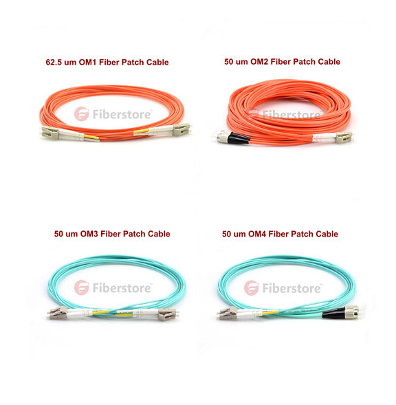
OM1 fiber optic cable is the 62.5/125 multimode fiber cable. OM1 fiber has a bigger core diameter, which makes it better at concentrating the light and bend-resistance. OM1 fiber was the indoor cabling standard chosen by AT&T, ANSI and IBM. For OM1 fiber cable, the max attenuation is 3.5dB/km working at 850nm, 1.5dB/km at 1300nm. Overfilled launch of OM1 fiber optic cable at 850nm is 200MHz*km, at 1300nm is 500MHz*km. Today, OM1 fiber optic cables are still a popular indoor use multimode fiber optic cable.
50µm Multimode Fiber Optic Patch Cords
50µm fiber includes OM2, OM3, OM4. OM2 fiber optic cable refer to the commonly used 50/125 traditional multimode fiber cable. OM1 and OM2 are both orange jacketed cable, and you cannot judge from the outer diameter to identify OM1 and OM2 fiber cable, because the 50/125 and 62.5/125 refer not to whole cable diameter but to the fiber inside. OM2 multimode fiber cables are used in fiber optic telecommunications and high speed transmission systems that require simultaneous, bi-directional data transfer.
OM3 cable and OM4 cable are both optimized for laser based equipment that uses fewer modes of light. As a result of this optimization, they are capable of running 10 Gigabit Ethernet at lengths up to 300m and 550m respectively. OM4 is completely backwards compatible with OM3 fiber and shares the same distinctive aqua jacket. OM4 was developed specifically for VSCEL laser transmission. OM4 multimode fiber optic cable is the highest level of multimode fiber optic cable that you can use. They can be used in networks where an overwhelming or extreme amount of data transfers will take place.
Which One Should You Choose?
Given its superior technical characteristics for high-speed links, 50μm fiber is the clear choice for new multimode fiber links in most circumstances. OM3-grade, high-bandwidth 50/125-micron fiber cable increases the flexibility of network designs and achieves data transfer rates up to 10Gbps at the lowest available cost. 50μm multimode fiber is the medium of the future, with 62.5μm fiber being supported chiefly for legacy purposes. However, the majority of the fiber deployed in the world today is 62.5μm, so backward compatibility is an important concern. On the other hand, there are no technical drawbacks to using different fiber types in separate network links, as long as the ports at both ends of the link are compatible with the cable. In a word, installing 50μm fiber for new network links is a good investment for future growth.
Multimode-fiber-patch-cable
Summary
With the increasing demand for network capacity, upgrades must be planned with an eye to the future. Installing 50μm multimode fiber today brings immediate benefits of longer cable reach and improved light loss budget margins, and prepares the network for future upgrades.

2016年3月24日星期四

Migrating to 40/100G Era with OM3 and OM4

To meet the continuously increased requirements, data center 40/100G migration is underway. The infrastructure of data centers for the 40G/100G should meet the requirements like high speed, reliability, manageability and flexibility. Fiber optic patch cable plays an important part. The cable used in data center must be selected to provide support for the higher needs of data rate. OM3 and OM4 fiber patch cables have gradually become the popular choice of data center during 40/100G migration. This article illustrates OM3/OM4 multimode fiber cables in 40/100G migration in details.
Why Choose OM3 and OM4 in 40/100G Migration?
OM stands for optical multimode. Why not single-mode fiber cables? The answer is the cost. The price of single-mode fiber is generally more expensive than multimode fiber. Multimode fiber utilizes low cost 850nm transceivers for serial and parallel transmission. Why not OM1 or OM2? Compared with OM1 and OM2, OM3 and OM4 can transport data at higher rate and longer distance. OM3 and OM4 are both laser-optimized multimode fibers with 50/125 core, which are designed for use with 850nm vertical-cavity surface-emitting laser (VCSEL) and are developed to accommodate faster networks such as 10, 40 and 100 Gbps. The IEEE 802.3ba 40/100G Ethernet Standard provides specific guidance for 40/100G transmission with multimode and single-mode fibers. OM3 and OM4 are the only multimode fibers included in the standard. The reason why OM3 and OM4 are applied in 40/100G migration is that they can meet the requirements for the migration cabling performance.
multimode fibers
Advantages of Utilizing OM3 and OM4
Bandwidth, transmission distance and total connector insertion loss are three main factors should be considered when evaluation the performance needed for cabling infrastructure to meet the requirements for 40/100G. Advantages of utilizing OM3 and OM4 in these three aspects will be explained below.
Higher Bandwidth: OM3 and OM4 are optimized for 850nm transmission and have a minimum 2000MHz∙km and 4700MHz∙km effective modal bandwidth (EMB). Comparing the OM1 and OM2 with a maximum of 500 MHz∙km, advantages of OM3 and OM4 are obvious.
Longer Transmission Distance: OM3 fiber and OM4 fiber can support longer transmission distance compare with other traditional multimode fibers. Generally OM3 fibers can run 40/100 Gigabit at 100 meters and OM4 fibers can run 40/100 Gigabit at 150 meters. This high data rate and longer distance cannot be achieved by other traditional multimode fiber like OM1 and OM2.
Lower Insertion Loss: According to the 40/100G standard, OM3 fiber is specified to a 100m distance with a maximum channel loss of 1.9dB, which includes a 1.5dB total connector loss budget. And OM4 fiber is specified to a 150m distance with a maximum channel loss of 1.5 dB, including a total connector loss budget of 1.0 dB. With low-loss OM3 and OM4 fiber, maximum flexibility can be achieved with the ability to introduce multiple connector mating into the connectivity link and longer supportable transmission distance can be reached.
OM3 or OM4?
OM3 and OM4 are both available for 40/100G applications. But you also need to choose which one to use. The applications and the total costs are always the main factors to consider to figure out whether OM3 or OM4 is needed. The connectors and the termination of the connectors for OM3 and OM4 fibers are the same. OM3 is fully compatible with OM4. The difference is just in the construction of fiber cable, which makes OM4 cable has better attenuation and can operate higher bandwidth at a longer distance than OM3. Thus, the cost for OM4 fiber is higher than OM3. As 90 percent of all data centers have their runs under 100 meters, choosing OM3 comes down to a costing issue. However, looking in the future, as the demand increases, the cost will come down. Thus, OM4 might be the most viable product at some point soon.
OM3-and-OM4
Conclusion
Migration to 40/100G has already been underway. With good performance like high data rate, long transmission distance and lower inserting loss, it seems that OM3/OM4 fiber cable is a must in data center migration to 40/100G.

2016年3月21日星期一

When to Use Multi-mode Fiber Optic Patch Cable?

Multi-mode fiber optic patch cable is a common used fiber jumper type. It has its own special advantages and applications. Knowing when to use a multi-mode fiber optic patch cable is very necessary for those who want to design a reliable and sustainable optical network. When to use multi-mode fiber optic patch cables? Here is what you need to consider if you are going to implement multi-mode fiber optic cable.
Introduction of Multi-mode Fiber Optic Patch Cable
Multi-mode fiber optic patch cable has a larger core diameter than singlemode fiber optic patch cable. There are two different core sizes of multi-mode fiber patch cords: 50 microns and 62.5 microns. Both 50 microns and 62.5 microns patch cable feature the same glass cladding diameter of 125 microns. For example, a 62.5/125µm multi-mode fiber patch cable has a 62.5µm core and a 125µm diameter cladding. The larger core of multi-mode fiber patch cords gathers more light and allows more signals to be transmitted at the same time. Transmission of many modes of light down a multi-mode fiber patch cable simultaneously causes signals to weaken over time and therefore travel short distance. So multi-mode fiber optic patch cables are used for data transmission over short distances.
multimode-fiber
Advantages of Using Multi-Mode Fiber Optic Patch Cable
Multi-mode fiber optic patch cables have a large carrying capacity. Signals can be transmitted without further needing to be refreshed or strengthened with the use of multi-mode fiber optic cable. These cables are also known for having a greater resistance to electromagnetic noise such as radios or motors or other nearby cables. Another major advantage of these fiber optic cables is that they cost much less to maintain than other types of fiber optic cable. A light-emitting diode (LED) or an injection-laser diode (ILD) are always used for generating the light pulses. Light is preferred for shorter distances, and 850nm is sufficient for most of these types of applications.
When to Use Multi-Mode Fiber Optic Patch Cable?
Knowing when to use a multi-mode fiber optic cable is half the battle of creating a winning design. Using it incorrectly can result in signal distortion or in another undesirable occurrence. You need to make the proper decision for your design or company to ensure that you will have optimal performance. Multimode fiber optic patch cable allows you to achieve greater speeds and larger bandwidths. It is recommended for signal transmission over medium distances. Multi-mode fiber patch cables can be used to connect high speed and legacy networks like Gigabit Ethernet, Fast Ethernet and Ethernet. OM1 and OM2 cables are commonly used in premises applications supporting Ethernet rates of 10Mbps to 1Gbps, which are not suitable though for today’s higher-speed networks. OM3 and OM4 are best multimode options of today. For prevailing 10Gbps transmission speeds, OM3 is generally suitable for distance up to 300 meters, and OM4 is suitable for distance up to 550 meters.
Conclusion
Knowing when to use a multi-mode fiber optic cable is not always that easy, but it can be determined by simply knowing how far the signal needs to be transmitted and the environment that the cable will be in during transmission. Fiberstore provides a wide range of fiber optic patch cables, both multi-mode fiber optic patch cables and singlemode fiber optic patch cables for your selections. We supply fiber optic patch cables with custom lengths with high quality.

2016年2月17日星期三

Choice of Bidirectional Transceivers for 40 GbE

As a result of data center consolidation, server virtualization, and new applications that require higher data transport rates, 10Gbps infrastructure is becoming overwhelmed by today's data center requirements, making the shift to 40 and 100 Gbps inevitable, especially in the network aggregation layer and core. How to upgrade the cabling infrastructure and migrate to the 40Gbps era in a cost-effective way? Cisco 40G QSFP (quad small form-factor pluggable) bidirectional (BiDi) technology provides a feasible and effective method, which will be introduced in the following text.
What Is 40G QSFP BiDi Transceiver?
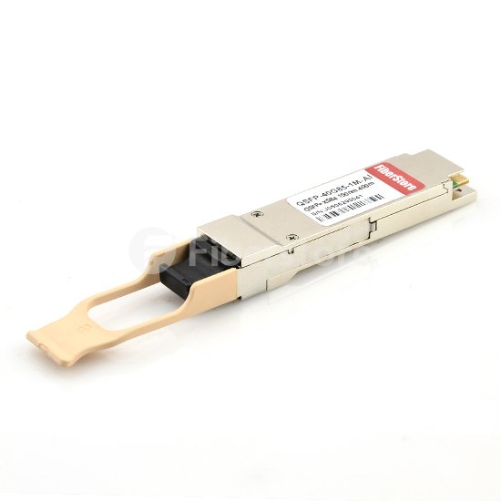
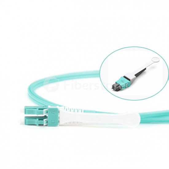
Cisco's innovative 40 Gbps QSFP BiDi transceiver is a pluggable optical transceiver with a duplex LC connector interface for short-reach data communication and interconnect applications. The Cisco BiDi transceiver supports link lengths of 100m and 150m on laser-optimized OM3 and OM4 multimode fibers. It complies with the QSFP MSA specification, enabling customers to use it on all QSFP 40 Gbps platforms to achieve high-density 40 Gigabit Ethernet networks.
How Does 40G QSFP BiDi Transceiver Work?
Cisco QSFP BiDi transceiver technology converts four channels each of 10Gbps transmit and receive signals to two bidirectional channels of 20Gbps signals, which means that the Cisco QSFP BiDi transceiver has two 20Gbps channels, each transmitted and received simultaneously over two wavelengths on a single MMF strand. The technology uses specialized, multilayer, thin-film dielectric coating and lensing, which allows components to both pass and reflect optical signals at the same time. And it uses Bidirectional Optical Sub-Assembly (BOSA) technology to support two wavelengths (20 Gbps total) on each fiber. The connection can reach 100 meters on OM3 MMF or 150 meters on OM4 MMF, which is the same as 40Gbps SR4. Picture below shows the technology concept of the Cisco QSFP BiDi transceiver.
Concept of Cisco QSFP BiDi Transceiver
Why Choose 40Gbps QSFP BiDi Transceiver?
The Cisco QSFP BiDi transceiver transmits full-duplex 40Gbps traffic over one dual-fiber LC connector OM3 or OM4 MMF cable. It provides the capability to reuse 10Gbps fiber infrastructure. In other words, it enables data center operators to upgrade to 40Gbps connectivity without making great changes to the previous 10Gbps fiber cable plant. By using the existing 10 Gigabit Ethernet duplex multi-mode fiber (MMF) infrastructure for 40 Gigabit Ethernet, the Cisco BiDi transceiver offers significant cost savings and simplifies data center upgrading. It allows for zero-cost fiber migration by reusing the current 10Gbps cabling for 40Gbps device connectivity. 40Gbps QSFP BiDi transceiver reduces overall costs and installation time for customers migrating data center aggregation links to 40Gbps connections. Using Cisco BiDi transceivers offers 75% less fiber and MPO requirements, reduced cable sprawl and rack footprints, and investment protection with future support for 100 Gbps over duplex fiber.
Conclusion
Cisco 40G QSFP BiDi technology removes 40Gbps cabling cost barriers for migration from 10Gbps to 40Gbps connectivity in data center networks. It is quite a competitive option among all those various choices for 40 Gigabit Ethernet applications, such as QSFP+ transceiver, QSFP+ breakout cable or active optical cable. Compared with them, Cisco 40G QSFP BiDi transceivers provide simpler and less expensive 40Gbps connectivity compared to other 40Gbps transceiver solutions. Anyway, you choose the most appropriate one for your applications.

2016年2月15日星期一

Things to Know about 40GBASE-SR4 QSFP+ Modules

With the growing demand for high data rates, 40 Gigabit Ethernet (GbE) is now becoming more and more widely adopted. For a 40 GbE network application, precise connectivity is crucial. 40G QSFP (quad small form factor pluggable) portfolio offers customers a wide variety of high-density and low-power 40 Gigabit Ethernet connectivity options. Among them, 40GBASE-SR4 QSFP+ transceiver is a common 40 GbE connectivity option. And here are some things that you need to know about 40GBASE-SR4 QSFP+ transceivers.
Introduction
40GBASE-SR4 is a fiber optic interface for multimode fiber of OM classes 3 and 4 with four parallel OM3 or OM4 fibers in both directions. “S” means short, indicating that it is an interface for short distances. The “R” denotes the type of interface with 64B/66B encoding and the numeral 4 indicates that the transmission is carried out over a ribbon fiber with four multimode fibers in every direction. Each lane has a 10 Gbit/s data rate. 40GBASE-SR4 QSFP+ modules usually use a parallel multimode fiber (MMF) link to achieve 40G. It offers 4 independent transmit and receive channels, each capable of 10G operation for an aggregate data rate of 40G over 100 meters of OM3 MMF or 150 meters of OM4 MMF. It primarily enables high-bandwidth 40G optical links over 12-fiber parallel fiber terminated with MPO/MTP multifiber female connectors.
40GBASE-SR4 QSFP+ module can also be used in a 4x10G mode for interoperability with 10GBASE-SR interfaces up to 100 and 150 meters on OM3 and OM4 fibers, respectively. The worry-free 4x10G mode operation is enabled by the optimization of the transmit and receive optical characteristics to prevent receiver overload or unnecessary triggering of alarm thresholds on the 10GBASE-SR receiver, and at the same time is completely interoperable with all standard 40GBASE-SR4 interfaces. The 4x10G connectivity is achieved using an external 12-fiber parallel to 2-fiber duplex breakout cable, which connects the 40GBASE-SR4 module to four 10GBASE-SR optical interfaces. The picture below shows a Mellanox MC2210411-SR4 compatible 40GBASE-SR4 QSFP+ transceiver.
Mellanox MC2210411-SR4 Compatible 40GBASE-SR4 QSFP+ Transceiver
40GBASE-SR4 QSFP+ Module vs 40GBASE-CSR4 QSFP+ Module
40GBASE-CSR4 QSFP+ module is similar to the 40GBASE-SR4 interface extends supported link lengths to 300m and 400m respectively on laser-optimized OM3 and OM4 multimode fiber cables. Each 10-gigabit lane of this module is compliant to IEEE 10GBASE-SR specifications. This module can be used for native 40G optical links over 12-fiber ribbon cables with MPO/MTP connectors, or in 4x10G mode with ribbon to duplex fiber breakout cables for connectivity to four 10GBASE-SR interfaces. Maximum channel insertion loss allowed is respectively 2.6dB over 300m of OM3 cable or 2.9dB over 400m of OM4 cable.
Conclusion
Fiberstore offers you a wide variety of 40GBASE-SR4 QSFP+ transceivers for your high-density and low-power 40 Gigabit Ethernet connectivity options branded by many famous companies like Cisco, Juniper or HP. And we also provide other compatible 40G QSFP+ transceivers, such as 40GBASE-LR4 QSFP+ transceiver, 40GBASE-ER4 QSFP+ transceiver, 40GBASE-CSR4 QSFP+ transceiver, etc. Every fiber optic transceiver provided by Fiberstore has been tested to ensure its compatibility and interoperability. You can buy from us with confidence.

2016年2月8日星期一

40 GbE and 100 GbE over Multimode Fiber

To support the changing and fast-growing bandwidth demands of data centers, the IEEE ratified standards for supporting 40 GbE (Gigabit Ethernet) and 100 GbE (Gigabit Ethernet), known as IEEE 802.3ba. Both 40 and 100 GbE can be deployed using the same cabling systems in use today. Multimode will employ parallel optics using MPO interconnects and require additional cable infrastructure depending on the system deployed while single mode fiber will employ serial transmission and use LC or SC connectors. Each has its own advantages and disadvantages. In this post, 40 GbE and 100 GbE over multimode fiber will be introduced.
40 GbE and 100 GbE Standard
IEEE published the IEEE 802.3ba standard for 40 Gigabit and 100 Gigabit Ethernet in June 2010. multimode optical fiber OM1, OM2, OM3 and OM4 have different capabilities of supporting different Ethernet applications. Only the laser optimized multimode fiber (grades OM3 and OM4) are capable of supporting 40G and 100G Ethernet. The next part will focus on the cabling requirements of 40 GbE and 100 GbE over multimode fiber. The table below shows 40GE and 100GE specifications.
40 GbE and 100 GbE Specifications
Implementing Parallel Optics
Traditionally, the Ethernet standard has relied upon duplex fiber cabling with each channel using one fiber to transmit and the other to receive. However, the 802.3ab standard requires multiple lanes of traffic per channel. To do this, the 40/100GbE standard uses parallel optics. The 802.3ba standard defines the parallel operation of four OM3/OM4 fibers for 40 GbE in 40GBASE-SR4 and the parallel operation of ten OM3/OM4 fibers for 100 GbE in 100GBASESR10. Two fibers have to be used per link because this arrangement is full duplex operation, i.e. simultaneous transmission in both directions. Therefore the number of fibers increases to eight for 40GBASE-SR4 and to 20 for 100GBASE-SR10. In the parallel optical link, the signal is split, transmitted over separate fibers and then joined again. That means the individual signals have to arrive at the receiver at the same time. Any skew in signal components has to be kept within tight tolerances. Trunk cables preterminated with MPO/MTP connectors are therefore the best choice for reliable transmission.
What Is 40 GbE and 100GbE over Multimode Fiber?
40G Ethernet and 100G Ethernet over multimode fiber uses parallel optics at 10 Gb/s per lane. One lane uses 1 fiber for each direction of transmission. 40G Ethernet requires 8 fibers. 100G Ethernet requires 20 fibers. The minimum performance that is needed to support 40 GbE and 100 GbE over multimode fiber is OM3 fiber for a distance of 100 meters. Cabling with OM4 fiber provides the capability to extend the reach up to 150 meters. Parallel optical channels with multi-fiber multimode optical fibers of the categories OM3 and OM4 are used for implementing 40 GbE and 100 GbE. The small diameter of the optical fibers poses no problems in laying the lines, and 802.3ba standard incorporated the MPO multi-fiber connector for 40GBASE-SR4 and 100GBASE-SR10, which can contact 12 or 24 fibers in the tiniest of spaces.
Conclusion
Optical fiber cabling is commonly deployed for backbone cabling in data centers for switch to switch connections and also for horizontal cabling for switch to server and storage area network connections. The use of pre-terminated optical fiber cabling can facilitate the migration path to 40G and 100G Ethernet in the future. Fiberstore can supply you with top-quality components for your 40 GbE and 100 GbE network, like 40G QSFP transceivers, and all kinds of QSFP+ cable choices, it also assists you competently with all questions involving planning, installation and maintenance.

2016年2月5日星期五

Introduction to MPO/MTP Technology in 40 GbE

The increasing demands of bandwidth and high speed drive the emergence of 40 GbE, and even up to higher in the future. And the high-speed transmission requires high-density data center as the increasing created data need amount of cables and devices which take a lot of space and cost. Data centers have to achieve ultra-high density in cabling to accommodate all this cabling in the first place. Multimode fiber optics is the medium of the future for satisfying the growing need for transmission speed and data volume over short distances. Ultra-parallel connections involve tougher requirements in terms of the components and the handling of the connectors. The MPO/MTP technology has proven to be a practical solution. This article provides introductory information on MPO/MTP technology in 40 GbE.
MPO/MTP—Multi-fiber Connectors for High Port Density
Parallel optical channels with multi-fiber multimode optical fibers of the categories OM3 and OM4 are used for implementing 40 GbE. The small diameter of the optical fibers poses no problems in laying the lines, but the ports suddenly have to accommodate four or even ten times the number of connectors. This large number of connectors can no longer be covered with conventional individual connectors. That is why the 802.3ba standard incorporated the MPO multi-fiber connector for 40GBASE-SR4. It can contact 12 or 24 fibers in the tiniest of spaces. Next part describes this type of connector.
12 Fibers 10G OM4 Harness Cable, 12 Strands, MPO-HD to LC-HD Push Pull TAB Connector
MPO Connectors: Structure and Function
The MPO connector (known as multi-fiber push-on and also as multi-path push-on) is a multi-fiber connector defined according to IEC 61754-7 and TIA/EIA 604-5 that can accommodate up to 72 fibers in the tiniest of spaces, comparable to an RJ45 connector. MPO connectors are most commonly used for 12 or 24 fibers. Eight fibers are needed for 40 GbE, which means four contacts remain non-interconnected in each case. MPO connectors and MTP (mechanical transfer push-on) connectors are no longer terminated on site because of the delicate multi-fiber structure and narrow tolerances involved. MPO/MTP connectors are therefore sold already terminated together with trunk cables. With this arrangement, customers have to plan line lengths precisely but are also assured top quality and short installation times. To achieve lower tolerances and better attenuation values, the American connectivity specialist US Conec developed the MTP connector. It has better optical and mechanical quality than the MPO. An MTP connector consists of a housing and a separate MT ferrule. The MT ferrule is a multi-fiber ferrule in which the fiber alignment depends on the eccentricity and positioning of the fibers and the holes drilled in the centering pins. The centering pins help control fiber alignment during insertion. Since the housing is detachable, the ferrules can undergo interferometric measurements and subsequent processing during the manufacturing process.
Conclusion
MPO/MTP connectors and fiber cables as the important part of the multi-fiber connection system, are designed for the reliable and quick operations in data centers. Fiberstore manufactures and distributes a wide range of MTP/MPO cable assemblies including trunk cables, harness cables and cassettes (or patch panels). And we also offer other kinds of transceiver and cable choices for your 40GbE applications, for example, HP JG709A 40GBASE-CSR4 QSFP+ transceiver, and Juniper QFX-QSFP-DAC-3M QSFP+ to QSFP+ passive copper cable, etc. Futhermore, customized service such as optional fiber counts, cable types and lengths are available.

2015年12月8日星期二

A Guide to 40 Gigabit Ethernet

The 802.3ba Ethernet standard introduced by the IEEE in June 2010 was in response to the increasing bandwidth demands facing data centers, paving the way for the introduction of 40Gb/s and 100Gb/s Ethernet operations. As you begin to think about the future of your network, understanding all the 40 Gigabit Ethernet (40GbE) and 100 Gigabit Ethernet (100GbE) optical components can be confusing. In this post, a brief overview of the current 40 Gigabit Ethernet to aid in planning for future high-performance Ethernet needs will be given.
What Is 40 Gigabit Ethernet?
40GbE is a standard that enables the transfer of Ethernet frames at speeds of up to 40 gigabits per second (Gbit/s). The 40GbE standard is intended for local server connectivity. One of the most attractive characteristics of 40 Gigabit Ethernet is broad applications and design flexibility. 40 Gigabit Ethernet runs on quad small form factor pluggable (QSFFP) cabling, a high-density fiber connector with 12 strands of fiber. According to the task force, 40GbE fulfills the following requirements and objectives:
  • Preserve existing 802.3 frame format, minimum size, and maximum size.
  • Support high-bandwidth applications such as video on demand (VoD) and high-performance computing (HPC).
  • Support high-speed switching, routing, and application functions in data centers.
  • Exhibit a bit error rate (BER) of 10-12 or better.
  • Provide support for optical transport network (OTN).
  • Provide specifications for operation over single-mode optical fiber, laser optimized multi-mode optical fiber, copper cables, and backplanes.
How Does 40 Gigabit Ethernet Work?
40 Gigabit Ethernet can be deployed using the same cabling systems in use today. Multi-mode will employ parallel optics using MPO interconnects and require additional cable infrastructure depending on the system deployed while single mode fiber will employ serial transmission and use LC or SC connectors. The approach used for the higher speed data rates is based on advanced transceiver technologies engineered to take advantage of the full bandwidth of laser optimized fibers. The 40 Gigabit Ethernet specification calls for a 12-fiber cabling solution, implemented using eight of the twelve fibers in an MPO connector, with each channel featuring four dedicated transmit fibers and four dedicated receive fibers. The middle four fibers remain unused, or dark. Each Tx/Rx pair is operating at 10G.
40 Gigabit Ethernet Cables
Cabling for 40 Gigabit Ethernet can be optical fiber or copper. The supportable channel length depends on the cable and the transceiver type. With regard to connectors, the only significant change outlined in the 802.3ba standard is the use of MPO (Multi-Fiber Push On) type connectors at the multi-mode transceivers to support the multi-fiber parallel optics channels. For data center environments operating at 40Gbps, OM3 and OM4 multi-mode cabling is generally recommended because its reach supports a wider range of deployment configurations compared to copper solutions, and the cost is lower compared to single-mode solutions.
40 Gigabit Ethernet Transceivers
40 Gigabit Ethernet transceivers are being developed along several standard form factors. The C form-factor pluggable (CFP) transceiver features 12 transmit and 12 receive 10Gbps lanes to support up to three 40 Gigabit Ethernet ports. Its larger size is suitable for the needs of single-mode optics and can easily serve multi-mode optics or copper as well. The CXP transceiver form factor also provides 12 lanes in each direction, but is much smaller than the CFP and serves the needs of multi-mode optics and copper. The quad small form-factor pluggable (QSFP) is similar in size to the CXP and provides four transmit and four receive lanes to support 40 Gigabit Ethernet applications for multi-mode fiber and copper. And quad small form-factor pluggable plus (QSFP+) gradually replaces QSFP and is widely used by people as it can provide higher bandwidth. The picture below shows a Cisco WSP-Q40GLR4L compatible QSFP+ transceiver.
Cisco WSP-Q40GLR4L Compatible 40GBASE-LR4L QSFP+ Transceiver
Migrating to 40 Gigabit Ethernet will prove very cost-effective for those who do it right. One critical step is to choose appropriate cables and transceivers. Fiberstore is a professional manufacturer and supplier, which offers a large amount of cables and transceivers for your 40GbE applications. For example, HP 805755-B21 compatible QSFP+ transceiver, and Juniper JNP-QSFP-4X10GE-IR compatible QSFP+ transceiver offered by Fiberstore are cost-effective and high-performance transceiver modules fully compatible with major brands.